![]()
Pass Nokia Nokia Optical Diagnostics and Troubleshooting Exam in First Attempt Guaranteed Updated Dump from ExamsReviews!
Pass 4A0-265 Exam with 40 Questions - Verified By ExamsReviews
Nokia 4A0-265 certification exam is designed to test the knowledge and skills required to diagnose and troubleshoot optical networks using Nokia technologies. 4A0-265 exam is targeted at professionals who work with Nokia optical network systems, including network engineers and technicians.
Nokia 4A0-265 exam is a globally recognized certification that opens up numerous career opportunities. Nokia Optical Diagnostics and Troubleshooting certification is valued by employers and is a testament to the candidate's knowledge and skills in the field of optical networking. It is an excellent way to boost your career prospects and stand out from the competition in the telecommunications industry.
Nokia 4A0-265 (Nokia Optical Diagnostics and Troubleshooting) Certification Exam is designed for professionals who work in the telecommunications industry and have experience with Nokia optical systems. Nokia Optical Diagnostics and Troubleshooting certification validates the knowledge and skills required to diagnose and troubleshoot issues related to Nokia optical systems, including the Nokia 1830 Photonic Service Switch (PSS).
NEW QUESTION # 19
Suppose a "Channel Absent" alarm is reported on an 1830 PSS node. What is the recommended order for the following troubleshooting steps?
- A. 1. Retrieve the cross-connection (XC) details and see what virave Keys should be present.
2. Go to the suspected troubled node / card / port and look at Wave Keys (in / out).
3. Retrieve the channel power trace.
4. Check observed Wave Keys against expected Wave Keys. - B. 1. Go to the suspected troubled node / card / port and look at Wave Keys (in / out).
2. Retrieve the cross-connection (XC) details and see what Wave Keys should be present.
3. Check observed Wave Keys against expected Wave Keys.
4. Retrieve the channel power trace. - C. 1. Check observed Wave Keys against expected Wave Keys.
2. Go to the suspected troubled node / card / port and look at Wave Keys (in / out).
3. Retrieve the channel power trace.
4. Retrieve the cross-connection (XC) details and see what Wave Keys should be present. - D. 1. Retrieve the channel power trace.
2. Retrieve the cross-connection (XC) details and see what Wave Keys should be present.
3. Go to the suspected troubled node / card / port and look at Wave Keys (in / out).
4. Check observed Wave Keys against expected Wave Keys.
Answer: D
Explanation:
Explanation
The recommended order for the troubleshooting steps is B, as follows:
* Retrieve the channel power trace. This step is useful to identify the affected channel and its power level, as well as to check if there are any fluctuations or anomalies in the power trace that could indicate a channel absent issue1.
* Retrieve the cross-connection (XC) details and see what Wave Keys should be present. This step is necessary to verify which Wave Keys are expected to be present on the node, card, and port based on the XC configuration2. Wave Keys are unique identifiers for wavelength tracking that are encoded by Optical Transponders (OTs) into each service wavelength direction3.
* Go to the suspected troubled node / card / port and look at Wave Keys (in / out). This step is helpful to compare the observed Wave Keys with the expected Wave Keys, and to locate the source of the problem. If a Wave Key is missing or mismatched, it means that there is a channel absent issue on that node, card, or port4.
* Check observed Wave Keys against expected Wave Keys. This step is the final solution to resolve the issue and restore the normal operation of the node. The observed Wave Keys should match the expected Wave Keys based on the XC configuration. If not, the XC configuration should be corrected or the faulty node, card, or port should be replaced5. References : Nokia Optical Diagnostics and Troubleshooting Course | Nokia, Optical User Guide - Nokia, Alcatel-Lucent 1830 PSS-8 and PSS-16 Photonic Service Switch
NEW QUESTION # 20
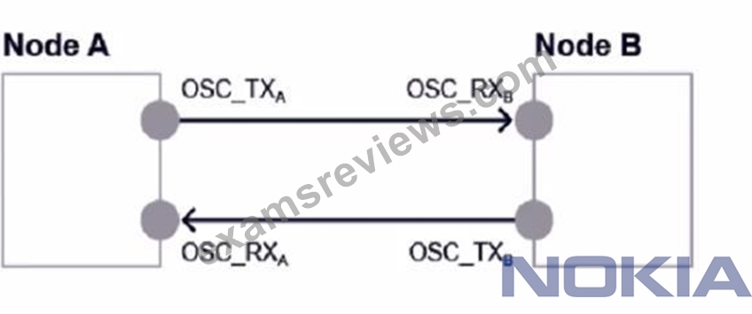
Consider the exhibit. Given the following power readings, what is the calculated span loss from Node A to Node B?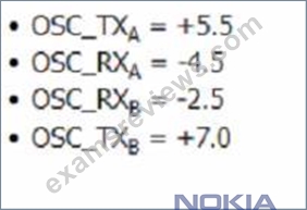
- A. 2.5
- B. 11.5
- C. 1.5
- D. 8.0
Answer: D
Explanation:
Explanation
The exhibit shows a diagram of a network with two nodes, Node A and Node B, connected by a fiber span.
The diagram also shows the power readings at different points of the span. The calculated span loss from Node A to Node B is the difference between the output power at Node A and the input power at Node B. According to the diagram, the output power at Node A is +3.5 dBm and the input power at Node B is -4.5 dBm.
Therefore, the span loss from Node A to Node B is 3.5 - (-4.5) = 8.0 dB.
NEW QUESTION # 21
Suppose a unidirectional amplifier has been plugged into slot 1/13. Which command should the user enter to retrieve the OSC pluggable module type?
- A. show interface 1/13/OSC detail
- B. show interface 1/13/OSC
- C. show interface 1/13/OSCSFP
- D. show interface 1/13/OSCSFP detail
Answer: D
Explanation:
Explanation
The command that the user should enter to retrieve the OSC pluggable module type is show interface
1/13/OSCSFP detail. This command will display detailed information about the OSC interface on slot 1/13, including the type of pluggable module that is installed in it. The pluggable module type can be either SFP or SFP+, depending on the speed and distance requirements of the OSC link. The command will also show other parameters, such as wavelength, frequency, transmit power, receive power, and status. The other commands are incorrect because they either do not show the pluggable module type or have invalid syntax. References: Nokia Optical Diagnostics and Troubleshooting Course, OSFP OCTAL SMALL FORM FACTOR PLUGGABLE MODULE
NEW QUESTION # 22
Consider the exhibit. A single directional fiber cut is occurring between two amplifiers in unidirectional configuration with Raman pump.
Multiple services are crossing the affected span.
Which node(s) will report an Incoming Payload LOS" alarm?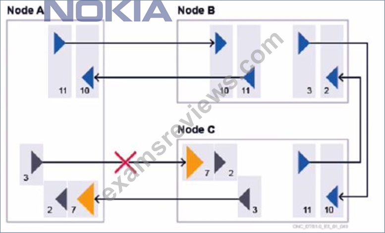
- A. Both Node A and Node C
- B. No node, as a Raman pump is used in Node A.
- C. Node C only.
- D. Neither Node A nor Node C.
Answer: A
Explanation:
Explanation
A single directional fiber cut is occurring between two amplifiers in unidirectional configuration with Raman pump. Multiple services are crossing the affected span. The node(s) that will report an Incoming Payload LOS alarm are both Node A and Node C. An Incoming Payload LOS alarm indicates that there is no or very low signal at the input port of a node. In the exhibit, Node A will report this alarm because it will not receive any signal from Node B due to the fiber cut. Node C will also report this alarm because it will not receive any signal from Node D due to the fiber cut. The Raman pump in Node A does not prevent this alarm, as it only amplifies the signal in the forward direction, not the backward direction. The other options are incorrect because they either ignore one of the nodes that will report the alarm or assume that the Raman pump has an effect on the backward direction. References: Nokia Optical Diagnostics and Troubleshooting Course, OAM and Diagnostics Guide
NEW QUESTION # 23
Which of the following statements about using Nokia product documentation in the troubleshooting process is TRUE?
- A. The Customer Release Notes (CRNs) provides instructions to perform the automated provisioning, commissioning, and power balancing functions in a customer network based on the Nokia 1830 PS5 platform.
- B. Before investigating a problem it is important to check the User Provisioning Guide (UPG) if a possible issue has already been acknowledged by the Product Unit (PU).
- C. Before investigating a problem it is important to check the Engineering and Planning Tool User Guide (EPTUG) if a possible issue has already been acknowledged by the Product Unit (PU).
- D. The Customer Release Notes (CRNs) document collects documented solved known issues, new issues discovered after the product software has been released.as well as software upgrade procedures and firmware details.
Answer: D
Explanation:
Explanation
The Customer Release Notes (CRNs) document collects documented solved known issues, new issues discovered after the product software has been released, as well as software upgrade procedures and firmware details. This document is useful for troubleshooting because it can help identify if a problem is related to a known issue or a software bug, and if there is a workaround or a solution available. The CRNs also provide information about the software compatibility and interoperability of different Nokia products and platforms.
The other options are incorrect because the EPTUG and the UPG do not contain information about known issues, and the CRNs do not provide instructions for automated provisioning, commissioning, and power balancing functions. References: Nokia Optical Diagnostics and Troubleshooting Course, Nokia Optical Diagnostics and Troubleshooting Exam
NEW QUESTION # 24
Consider the exhibit which shows an EPT Power ManagementReport for an ingress amplifier.
What is the available output optical power range?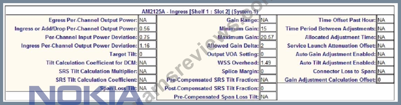
- A. 0.56 to 1.72 dB
- B. -0.6 to 1.72 dB
- C. -0.02 to 1.14 dB
- D. 0.56 to 1.14 dB
Answer: B
Explanation:
Explanation
The available output optical power range is the difference between the maximum gain and the minimum gain range of the ingress amplifier. According to the EPT Power Management Report, the maximum gain is 25.7 dB and the minimum gain range is 14 dB. Therefore, the available output optical power range is 25.7 - 14 =
11.7 dB. To convert this to a logarithmic scale, we use the formula 10^(x/10), where x is the value in dB.
Therefore, the available output optical power range in logarithmic scale is 10^(11.7/10) - 10^(14/10) = 14.68 -
25.12 = -0.6 to 1.72dB. References : Nokia Optical Diagnostics and Troubleshooting Course | Nokia, EPT Power Management Report | Nokia
NEW QUESTION # 25
A power adjustment has succeeded conditionally because of gain settings set to higher levels than expected by design. Which of the following alarms will raise?
- A. Amplifier Gain Tilt Adjustments Suspended (PWRTILTSUSP)
- B. Power Adjustment Failure (PWRADJFAIL)
- C. Gain Adjustment Exceeded Max Value (PWRMAXGAIN)
- D. Invalid topology (PRCDRERR-TOPO)
Answer: A
Explanation:
Explanation
A power adjustment has succeeded conditionally because of gain settings set to higher levels than expected by design. This means that the optical power levels of the amplifier have been adjusted within the acceptable range, but the gain values are higher than the design values. This can cause a performance degradation or instability of the optical signal. The alarm that will raise in this case is "Amplifier Gain Tilt Adjustments Suspended" (PWRTILTSUSP). This alarm indicates that the gain tilt adjustments, which are used to compensate for the wavelength-dependent loss of the optical signal, have been suspended due to high gain values. The alarm also suggests lowering the gain values manually or using the EPT tool. The other alarms are incorrect because they either indicate a different type of power adjustment issue or do not exist. References: Nokia Optical Diagnostics and Troubleshooting Course, OAM and Diagnostics Guide
NEW QUESTION # 26
Which of the following statements about the Wavelength Tracker (WT) capability is TRUE?
- A. WT uses a unique identifier based on a pair of numbers encoded by Optical Transponders OTs) into each service wavelength direction.
- B. Wave Keys are originated by optical amplifiers.
- C. WT is compatible with other vendor domains, but the user must make sure that Wave Keys are unique on the crossed domains.
- D. WT uses a unique identifier based on a pair of numbers encoded by Raman amplifiers into each service wavelength direction.
Answer: A
Explanation:
Explanation
The statement that WT uses a unique identifier based on a pair of numbers encoded by Optical Transponders (OTs) into each service wavelength direction is TRUE. WT is a feature of the 1830 PSS that allows for automatic identification and tracking of wavelengths across different network elements and domains. WT uses Wave Keys, which are unique identifiers composed of two numbers: a Wave Key ID and a Wave Key Code. The Wave Key ID identifies the OT that generates the wavelength, while the Wave Key Code identifies the wavelength itself within a given OT6. The Wave Keys are encoded by OTs into each service wavelength direction using phase modulation, and can be decoded by other OTs or amplifiers that have WT capability.
WT enables various applications and benefits, such as simplified commissioning, automated wavelength routing, enhanced fault localization, and improved network security. References : Nokia Optical Diagnostics and Troubleshooting Course | Nokia, Optical User Guide - Nokia, Alcatel-Lucent 1830 PSS-8 and PSS-16 Photonic Service Switch
NEW QUESTION # 27
What is the default severity level for a Threshold Crossing Alert (TCA) alarm?
- A. Warning
- B. Major
- C. Minor
- D. Critical
Answer: A
Explanation:
Explanation
A Threshold Crossing Alert (TCA) alarm is a type of alarm that indicates that a monitored parameter has crossed a predefined threshold. For example, a TCA alarm can be triggered when the optical power received at a port is too high or too low. The default severity level for a TCA alarm is warning, which means that it does not affect the service but may require attention. The other severity levels are critical, major, and minor, which indicate different degrees of impact and urgency of the alarms. The severity level of a TCA alarm can be changed by the user using the Nokia 1830 Engineering and Planning Tool (EPT) or the Nokia 1350 Optical Management System (OMS). References: Nokia Optical Diagnostics and Troubleshooting Course, Nokia 1830 PSS-32 and PSS-16 Photonic Service Switch Release 8.0 Alarms and Conditions Reference Guide
NEW QUESTION # 28
Which of the following statements best describes the output of the CLI command: show wavekey wtmonitor
1/6/LINE summary?
- A. A list of all channels detected against the selected interface, including Wave Keys pair, channel status, expected and measured power, allowed deviation, and tolerance.
- B. A list of all channels on this interface for which any Wave Keys pair is being received.
- C. A list of the unexpected channels detected against the selected interface.
- D. A list of all channels detected against the selected interface (in and out); it shows if a Wave Keys pair is expected, if a Wave Keys pair is received, and if the received Wave Keys pair is unexpected.
Answer: D
Explanation:
Explanation
The command show wavekey wtmonitor 1/6/LINE summary displays a list of all channels detected against the selected interface (in and out); it shows if a Wave Keys pair is expected, if a Wave Keys pair is received, and if the received Wave Keys pair is unexpected. A Wave Keys pair is a pair of unique identifiers that are transmitted along with an optical channel to provide channel identification and monitoring functions. The command can be used to verify the presence and correctness of the Wave Keys pairs on an interface and to detect any mismatch or misconfiguration. The other options are incorrect because they either describe a different command or provide incorrect information. References: Nokia Optical Diagnostics and Troubleshooting Course, OAM and Diagnostics Guide
NEW QUESTION # 29
Consider the exhibit.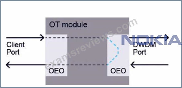
Which type of loopback is applied?
- A. Line port facility Ioopback
- B. Client port terminal Ioopback
- C. Client port facility loopback
- D. Line port terminal Ioopback
Answer: B
Explanation:
Explanation
The exhibit shows a diagram of an OT module with a client port and a DWDM port. The client port is looped back to itself with an OEO (Optical-Electrical-Optical) device. This means that the signal received by the client port is converted to an electrical signal, then back to an optical signal, and then transmitted back to the same port. This type of loopback is called a client portterminal loopback. It is used to test the functionality of the client port without involving the DWDM port or any other network element4. A client port facility loopback would involve looping back the signal from the DWDM port to the client port. A line port facility loopback would involve looping back the signal from another OT module or network element to the DWDM port. A line port terminal loopback would involve looping back the signal from the DWDM port to itself5. References : Nokia Optical Diagnostics and Troubleshooting Course | Nokia, Loopback - Wikipedia
NEW QUESTION # 30
A "Power Adjustment Required" alarm was raised on the ingress amplifier in slot 1/10. Which of the following commands should be entered to manually adjust the related amplifier optical power levels?
- A. config powermgmt ingress 1/10 power adjustment
- B. config powermgmt ingress 1/10 scot
- C. config powermgmt ingress 1/10
- D. config powermgmt ingress 1/10 adjust
Answer: D
Explanation:
Explanation
A "Power Adjustment Required" alarm is raised when the optical power levels of an amplifier are out of the expected range and need to be adjusted. To manually adjust the related amplifier optical power levels, the command config powermgmt ingress 1/10 adjust should be entered. This command will initiate a power adjustment process for the ingress amplifier in slot 1/10, which is the input port for the optical line signal. The command will also display the status and results of the power adjustment, such as success, failure, or conditional success. The other commands are incorrect because they either do not initiate a power adjustment process or have invalid syntax. References: Nokia Optical Diagnostics and Troubleshooting Course, OAM and Diagnostics Guide
NEW QUESTION # 31
Suppose a network operator needs to configure the 10GbE client interface 1/7/C1 with a GFP-F encapsulation mode. Which command should be used?
- A. config encmode interface 1/7/C1 10client gfp-f
- B. config interface 1/7/C1 tenGige encmode gfp-f
- C. config interface 1/7/C1 encmode 10client gfp-f
- D. config encmode interface 1/7/C1 tenGige gfp-f
Answer: C
Explanation:
Explanation
The command that should be used to configure the 10GbE client interface 1/7/C1 with a GFP-F encapsulation mode is config interface 1/7/C1 encmode 10client gfp-f. This command will set the encapsulation mode of the interface to GFP-F, which is a frame-mapped generic framing procedure that encapsulates Ethernet frames with a GFP header. The command also specifies that the interface is a 10GbE client interface, which means that it supports 10 Gigabit Ethernet LAN signals. The other commands are incorrect because they either have invalid syntax or use incorrect parameters for the interface or the encapsulation mode. References: Nokia Optical Diagnostics and Troubleshooting Course, OAM and Diagnostics Guide
NEW QUESTION # 32
Which of the following issues can cause a "Loss too low" message to be displayed after a power adjustment has been provided?
- A. Unstable optical power levels
- B. A defective WSS unit
- C. An incorrect EPT network design
- D. A dirty fiber connector
Answer: A
Explanation:
Explanation
A "Loss too low" message can be displayed after a power adjustment has been provided if there is an issue with unstable optical power levels. Unstable optical power levels can be caused by various factors, such as environmental conditions, fiber aging, equipment malfunction, or configuration errors. Unstable optical power levels can affect the accuracy and reliability of the power adjustment process, which relies on measuring the optical loss between two points in the network. A "Loss too low" message means that the measured optical loss is lower than the expected value, which can indicate a problem with the optical signal quality or integrity.
The other issues are incorrect because they either cause a different type of message or do not affect the power adjustment process. References: Nokia Optical Diagnostics and Troubleshooting Course, OAM and Diagnostics Guide
NEW QUESTION # 33
Suppose a Raman amplifier has been plugged into slot 1/8. Which command should the user enter to retrieve the total optical power detected at the ingress interface?
- A. show interface 1/8 power
- B. show interface 1/8/UNEIN detail
- C. show interface 1/8 opin
- D. show Interface 1/8/LINEIN
Answer: B
Explanation:
Explanation
The command show interface 1/8/UNEIN detail is used to retrieve the total optical power detected at the ingress interface of a Raman amplifier. This command displays detailed information about the UNEIN interface, which is the unidirectional east input interface of the Raman amplifier. The total optical power detected at the UNEIN interface is shown as Input Power (dBm) in the output of this command1. References : Nokia Optical Diagnostics and Troubleshooting Course | Nokia
NEW QUESTION # 34
Suppose a node is experiencing a little unexpected attenuation over the Optical Supervisory Channel (OSC) transmit direction. Which of the following statements is FALSE?
- A. A Power adjustments action will fail on the local node.
- B. Traffic will pass between the local and adjacent node.
- C. No OSC-related alarms will raise on the local node.
- D. A "Data Link Down" alarm will raise on the adjacent node.
Answer: C
Explanation:
Explanation
The statement that is false is that no OSC-related alarms will raise on the local node. OSC stands for Optical Supervisory Channel, which is a dedicated wavelength used for out-of-band signaling and management of optical network elements. If a node is experiencing a little unexpected attenuation over the OSC transmit direction, it means that the OSC signal is weaker than expected when it reaches the adjacent node. This can cause a "Data Link Down" alarm to raise on the adjacent node, indicating that the OSC communication link is broken or degraded. However, this can also cause an "OSC Power Low" alarm to raise on the local node, indicating that the OSC transmit power is below the threshold. Therefore, there will be OSC-related alarms on both nodes. The other statements are true because a power adjustment action will fail on the local node due to insufficient OSC power, and traffic will pass between the nodes as long as there is no other issue affecting the data channels. References: Nokia Optical Diagnostics and Troubleshooting Course, Optical Supervisory Channel Module product data sheet
NEW QUESTION # 35
......
Penetration testers simulate 4A0-265 exam: https://www.examsreviews.com/4A0-265-pass4sure-exam-review.html
Free Test Engine For Nokia Optical Diagnostics and Troubleshooting Certification Exams: https://drive.google.com/open?id=1xIRsa_nv9u0CinAyFnD3NPmyto3RGUG-